Leash App
Arc Eye Leash is the desktop application that provides complete control over your WOLF ONE system.
Connect to a single node via USB and automatically access every device in your HowlNET network.
System Requirements
| Platform | Requirement |
|---|---|
| macOS | macOS 10.14+ (Apple Silicon) |
| Windows | 10+ (64-bit) |
| Connection | USB Type-C to WOLF ONE |
Getting Started
Connecting to Leash
- Connect USB Type-C cable from computer to WOLF ONE node
- Open Arc Eye Leash desktop app
- WOLF auto-connects (check upper left dropdown if not detected)
If you have multiple nodes daisy-chained, connect USB to the first node in the chain (Director). All other nodes will be accessible through HowlNET.
Interface Overview
The Leash app is organized into tabs for different functions:
| Tab | Purpose |
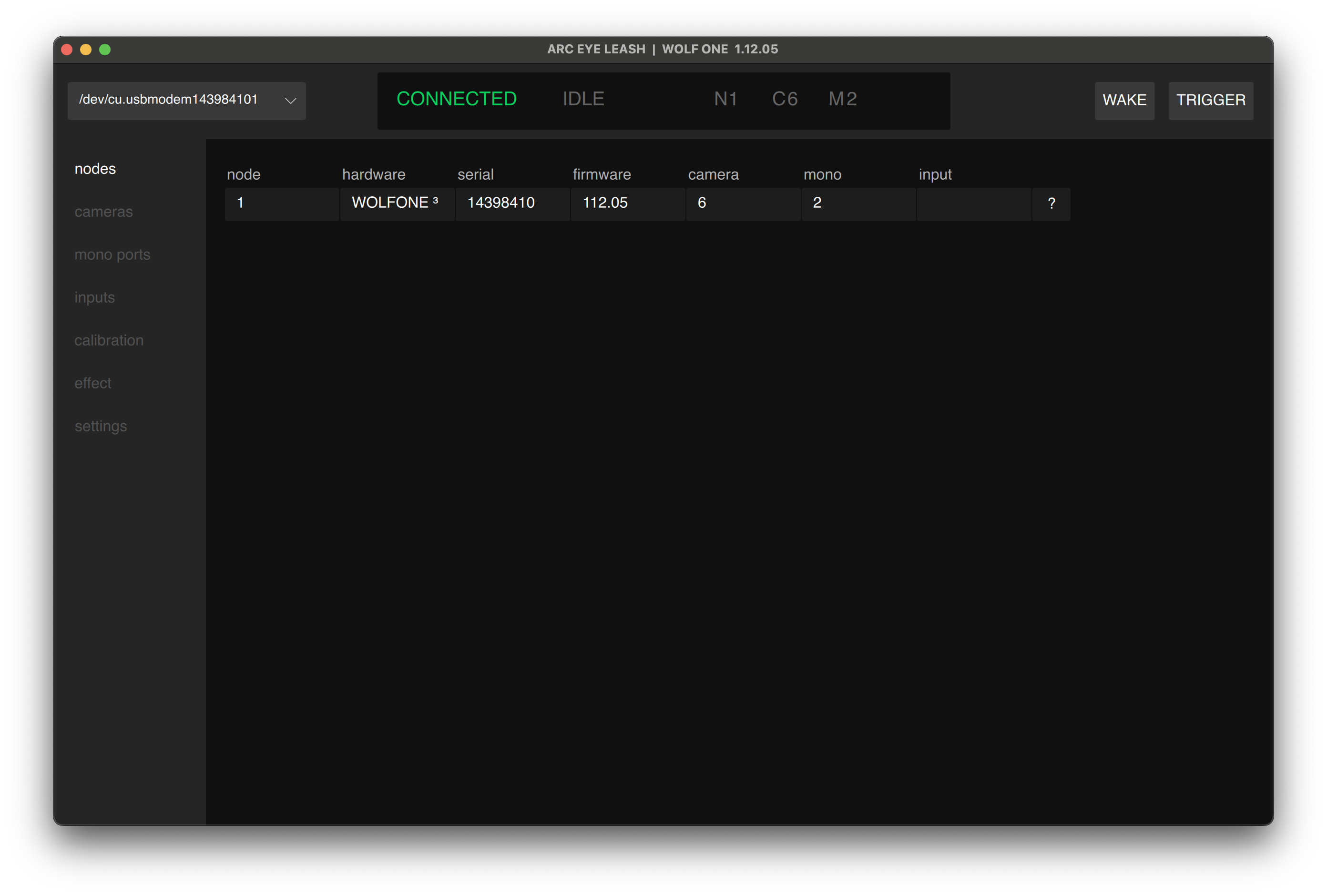
|---|---|
| Nodes | View connected nodes |
| Cameras | View and configure camera ports |
| Mono Ports | View and configure strobe / general purpose outputs |
| Calibration | Sync devices with different timing |
| Effects | Build custom trigger sequences |
| Settings | WOLF info, backup, restore, and firmware updates |
Top Bar
The top bar provides system-wide status and control:

1. Connection (Upper Left)
USB Serial Port Selector
- Shows connected node's serial port
- Switch between multiple USB-connected nodes
- Empty if no node detected
2. Status Bar (Center)
HowlNET System Status
| Status | Color | Meaning |
|---|---|---|
| IDLE | Grey | Ready to trigger |
| ORDERING | Blue | Network synchronizing order |
| CALCULATING | Blue | Effect calculation in progress |
| CALIBRATING | Blue | Camera calibration running |
| WAKE | GREEN | Wake signal active |
| TRIGGER | — | Trigger signal active |
System Information
- N# - Total HowlNET nodes detected
- C# - Total cameras across all nodes
- M# - Total mono ports across all nodes
2. EFFECT CONTROLS
WAKE/TRIGGER
- WAKE - AF cameras, effectively arming the system. (toggle)
- TRIGGER - Activate effect, typically triggering cameras (momentary)
- CANCEL - Cancel active effect (appears when effect is running)
Cameras Tab
View and manage all camera ports across your entire HowlNET system.
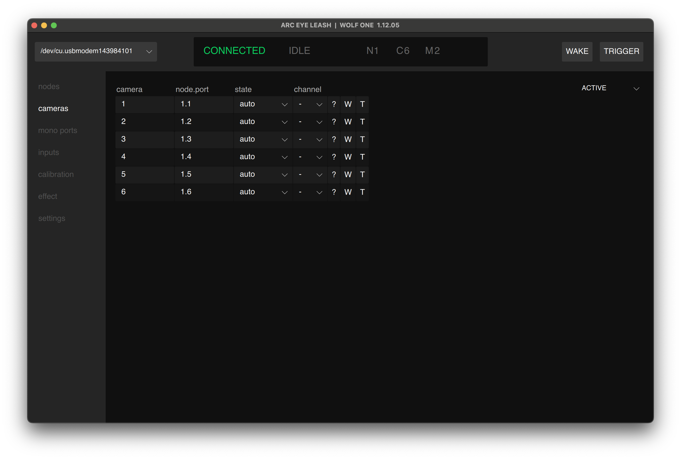
Camera List
Each camera shows:
- Camera - Auto-assigned sequential number
- Node.Port - Physical location (e.g., "1.3" = node 1, Port 3)
- State - disable port, automatic mode, always activated
- Calibration Channel - Corresponds to calibrations tab channels
- ? Button - Ping port (rainbow color LED)
- W/T Buttons - Individual Wake/Trigger for testing
Group cameras by model and settings for best sync results. Different camera models typically need different calibration channels.
Mono Ports Tab
Manage mono output ports - typically used for strobes and lighting.
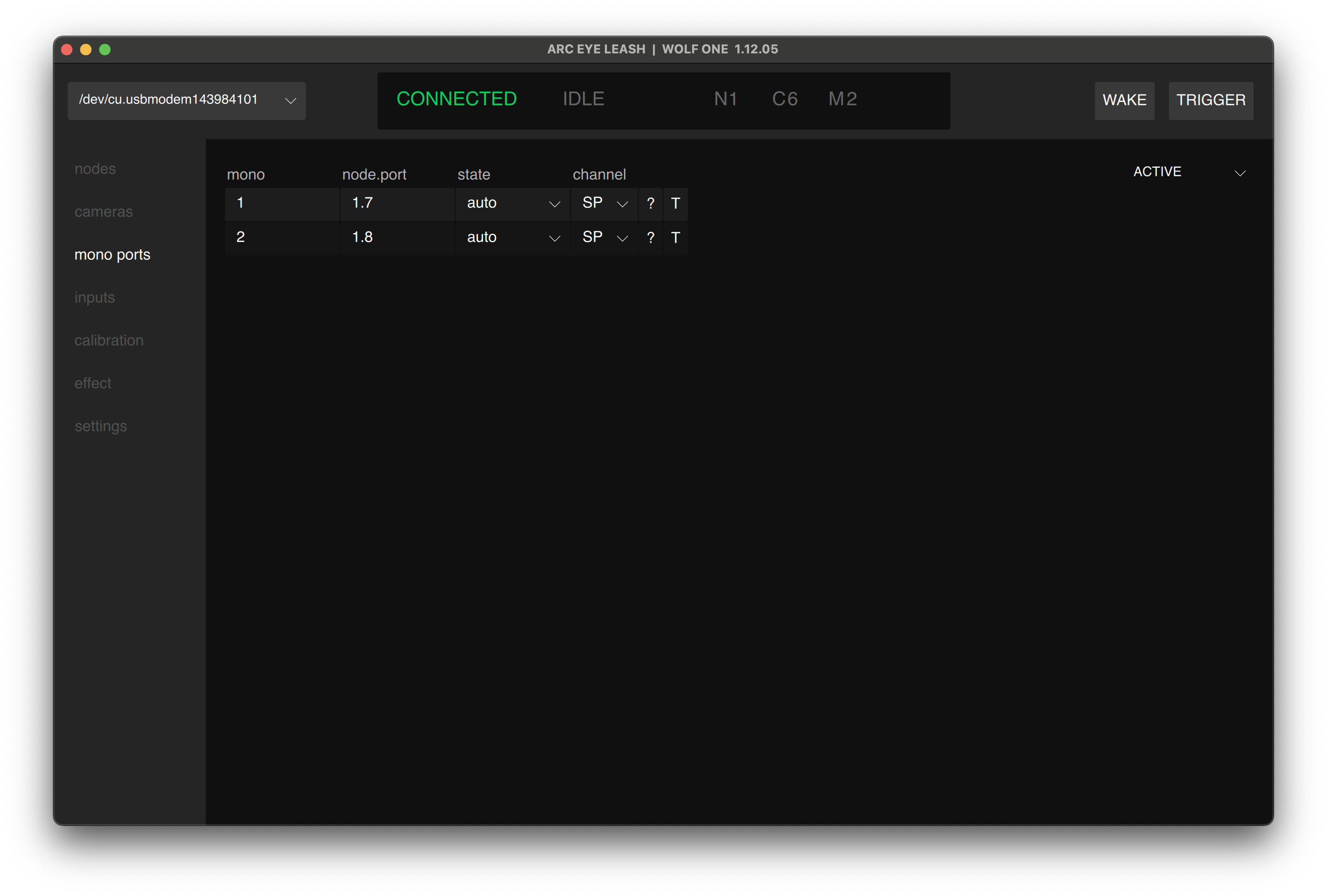
Mono Port List
Each mono port shows:
- Mono - Auto-assigned sequential number
- Node.Port - Physical location (e.g., "1.7" = node 1, Port 7)
- State - disable port, automatic mode, always activated
- Calibration Channel - Usually SP for strobes
- ? Button - Ping port (rainbow color LED)
- T Button - Individual Wake/Trigger for testing
Typical Uses
- Studio strobes
- Speedlights via wireless trigger
- External relay control
- Custom trigger devices
Most strobes should use the SP (Syncpoint) calibration channel for proper flash sync.
Input Tab
Manage input ports - external input for Wake (AF) and Trigger (starting effects)
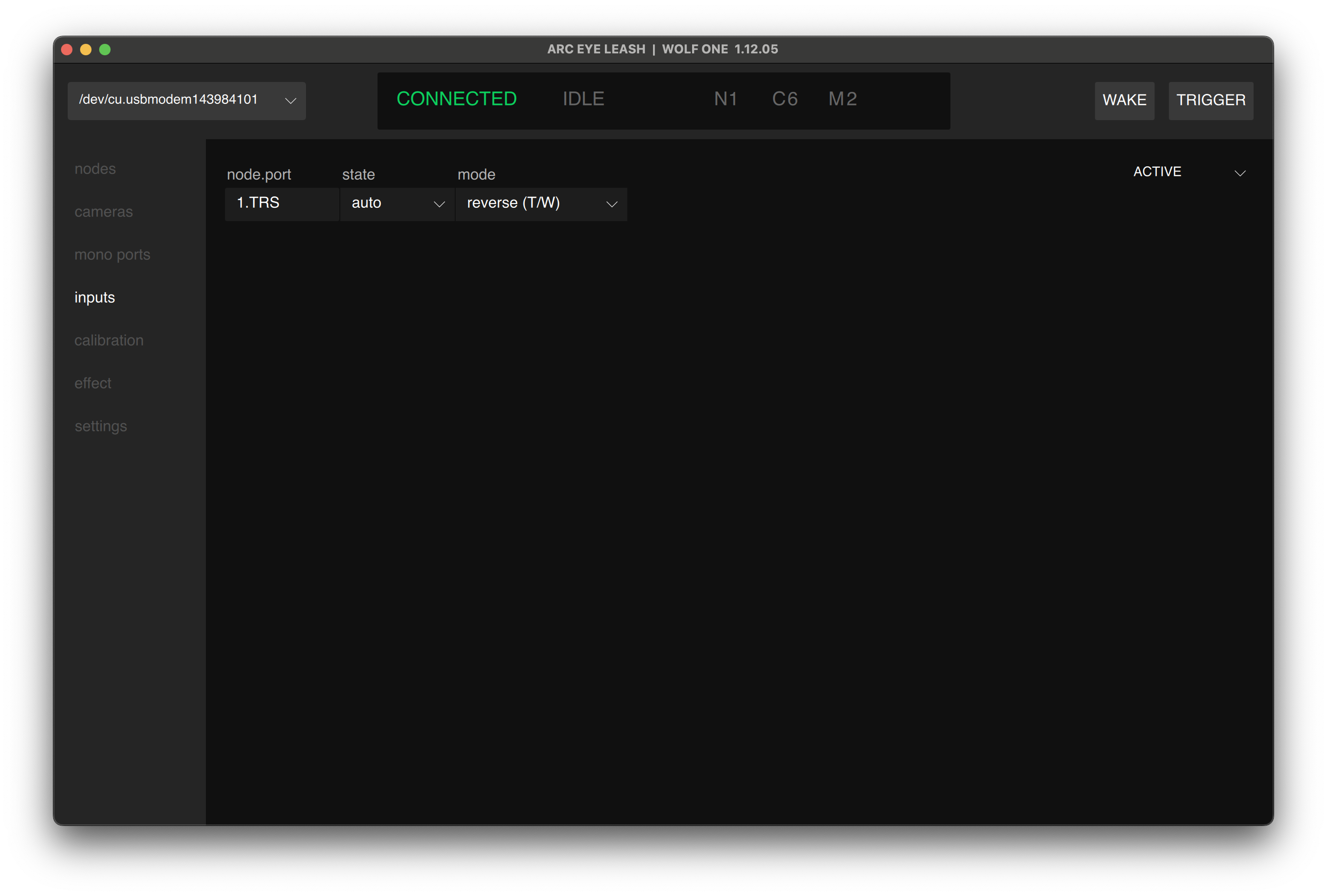
Input Device List
Each mono port shows:
- Position - Ordered position, visible in ALL filter mode
- Node.Port - Physical location (e.g., "1.TRS" = node 1, Port TRS)
- State - disable port, automatic mode, always activated
- mode - normal, reverse, both wake, both trigger
Compatible Devices
- Arc Eye Handheld controller
- Momentary Buttons
- Switches
- Custom trigger devices
- Relays
3.3v trigger signal. Do not apply an external voltage to this connector.
Calibration Tab
Synchronize cameras with different shutter lag characteristics.
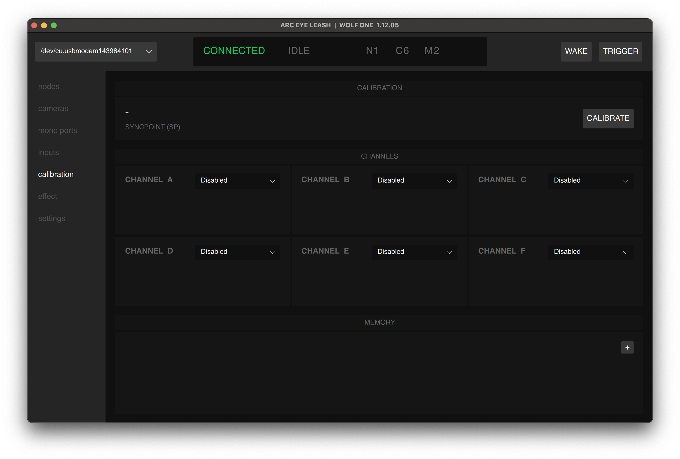
How Calibration Works
Each channel (AB,C,D,E,F) can store timing offsets to synchronize cameras:
- Measure shutter lag for camera model
- Calculate offset needed for sync
- Store offset in calibration channel
- Assign channel to cameras of that model
Quick Start
- SP (Syncpoint): Use for strobes and reference devices
- A-F Channels: Use for cameras and devices with different timing
- Automatic: Leash calculates offsets automatically
For detailed calibration instructions, see:
Effects Tab
Create custom trigger sequences that run independently on the node.
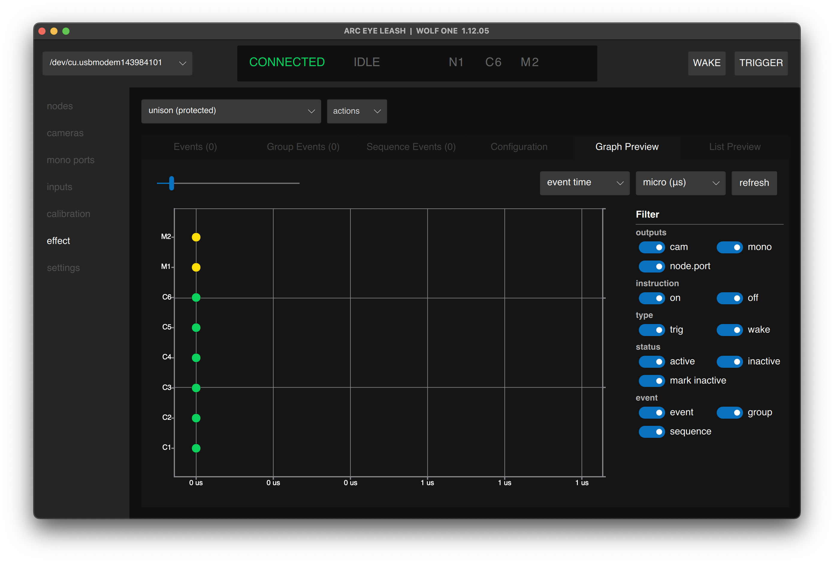
Effect Features
- WOLF storage - Effects run without computer connection
- Dynamic - Automatically adapt to connected nodes and devices
- Sequence - Create complex multi-camera patterns
Effect Types
- Synchronized 3D - All cameras at once
- Bullet-time - Sequential camera firing
- Burst Capture - Burst cameras at any framerate
- Custom patterns - Any timing sequence you need
For effect building tutorials, see:
Settings Tab
View WOLF information, backup/restore, and update firmware.
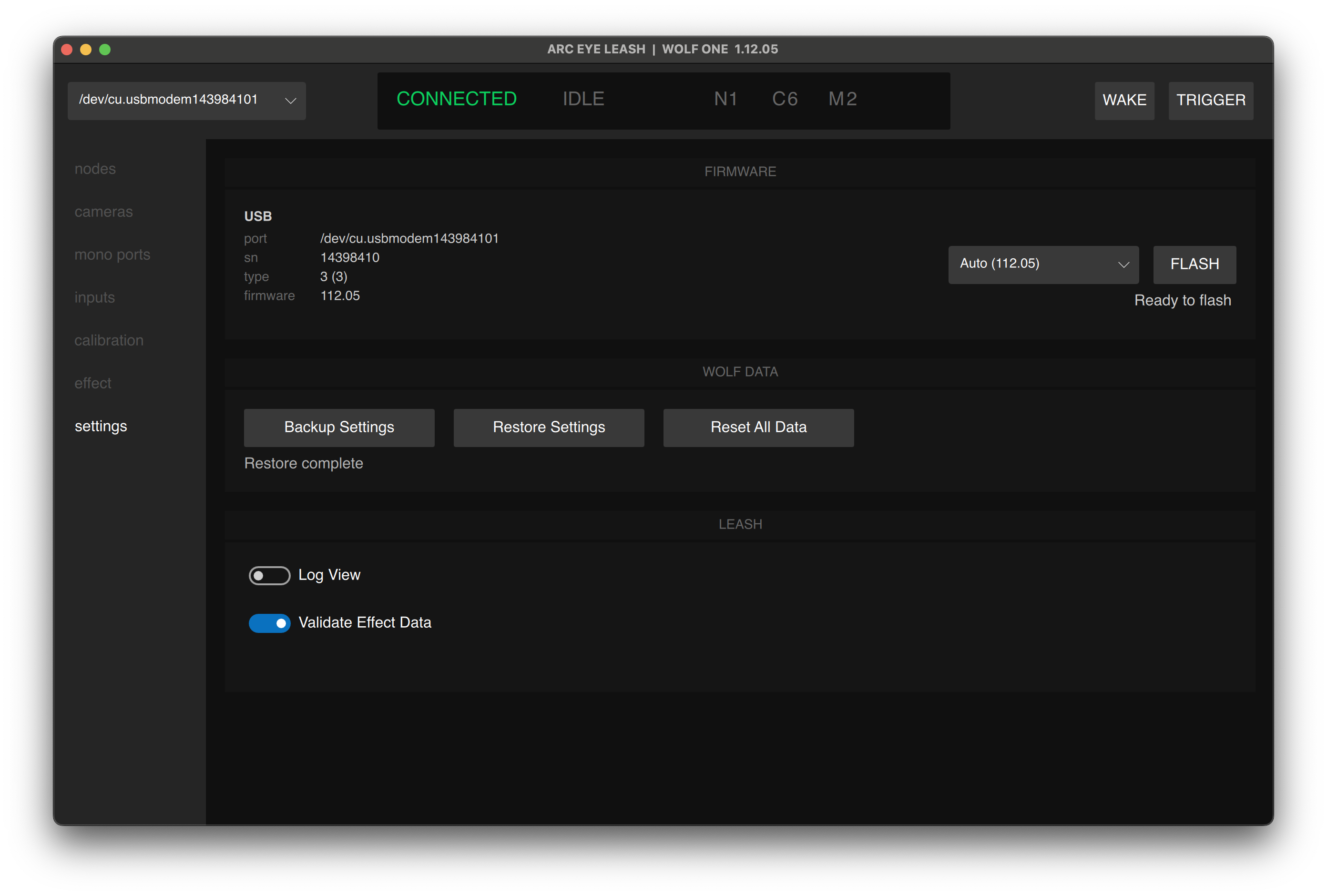
Node Information
- Firmware version - Current firmware running
- Hardware information - Physical board version, serial number, connection port
- Backup & Restore - Backup and restore WOLF configurations
- Leash - View realtime device log and other options
Important: Disconnect 24V DC bus power before flashing firmware. USB power only during flash.
For detailed firmware update instructions, see:
Quick Reference
Common Tasks
| Task | Steps |
|---|---|
| Test camera trigger | Cameras tab → toggle WAKE on → then click camera T button |
| Assign port calibration | Cameras tab → select channel dropdown |
| Run auto-calibration | Calibration tab → click CALIBRATE |
| Create new effect | Effects tab → actions dropdown → New... |
| Update firmware | Settings tab → click FLASH button |
Troubleshooting
Node is not detected
- Check USB cable connection
- Try different USB port on computer
- Try different USB cable
- Check device dropdown (upper left) for other ports
- Restart Leash App
HowlNET nodes Missing
- Verify HowlNET cable connections
- Check 24V power to first node
- Ensure daisy-chain direction (OUT → IN)
- Power cycle entire system
Cameras Not Responding
- Verify camera cable connections
- Ensure camera is in correct mode
- Test with W/T buttons in Cameras tab
For more troubleshooting help, see:
Next Step
Having issues? See Troubleshooting